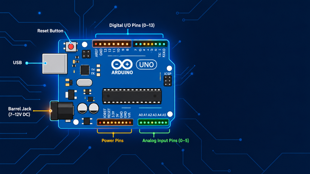
The Arduino Uno has 20 usable pins in total: 14 digital I/O pins (labeled 0–13, of which 6 support PWM output), 6 analog input pins (A0–A5), plus dedicated power pins (5V, 3.3V, GND, VIN) and communication pins for I2C, SPI, and UART. Each pin has a specific voltage limit, current limit, and function that must be understood before wiring any component, since incorrect connections can damage the board or the ATmega328P microcontroller.
Key takeaways
- Arduino Uno has 20 usable I/O pins: 14 digital + 6 analog.
- 6 digital pins (3, 5, 6, 9, 10, 11) support PWM (Pulse Width Modulation) for analog-like output.
- Analog pins (A0–A5) can also be used as digital pins if needed.
- Each I/O pin supplies a maximum of 20mA safely (40mA absolute max) exceeding this can damage the board.
- Power pins provide 5V and 3.3V regulated output for sensors and modules.
- Pins 0 and 1 (RX/TX) are used for serial communication and should be avoided while uploading code.
Arduino Uno pin diagram (labeled)
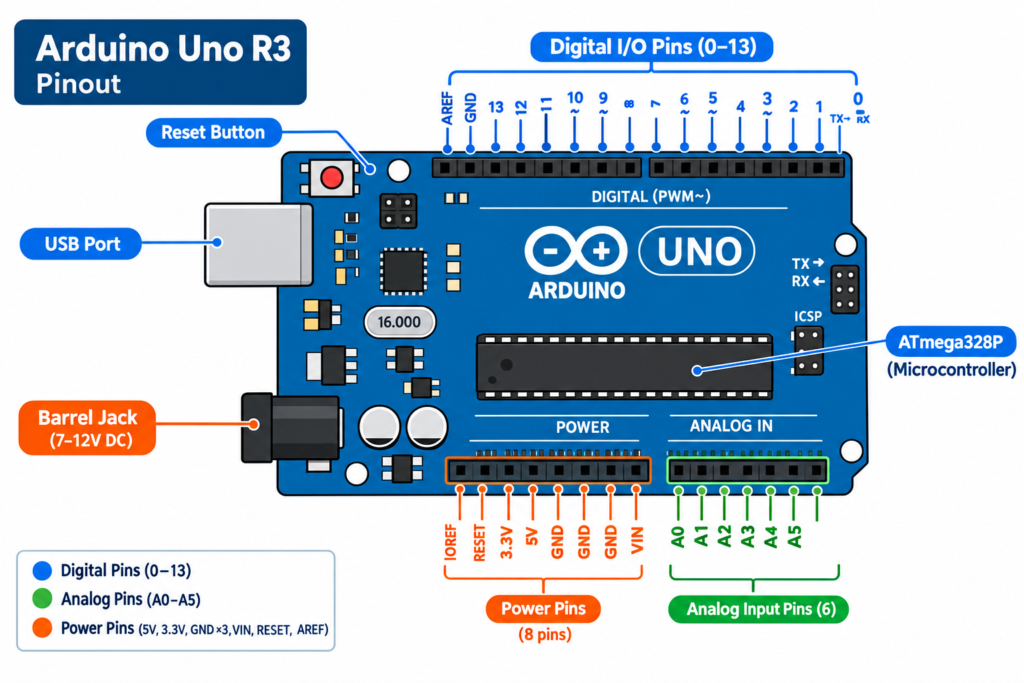
The diagram above shows the physical layout of every pin on the Arduino Uno, organized into four functional groups: digital pins (top edge), power pins (bottom-left), analog pins (bottom-right), and the ATmega328P microcontroller at the center, which processes all input/output logic.
Arduino Uno pinout: Full pin table
| Pin | Type | Function |
|---|---|---|
| 0 (RX) | Digital | Serial receive used for UART communication |
| 1 (TX) | Digital | Serial transmit used for UART communication |
| 2 | Digital | General I/O, supports external interrupt |
| 3 | Digital (PWM) | General I/O, PWM output |
| 4 | Digital | General I/O |
| 5 | Digital (PWM) | General I/O, PWM output |
| 6 | Digital (PWM) | General I/O, PWM output |
| 7 | Digital | General I/O |
| 8 | Digital | General I/O |
| 9 | Digital (PWM) | General I/O, PWM output |
| 10 | Digital (PWM) | General I/O, PWM output, SPI (SS) |
| 11 | Digital (PWM) | General I/O, PWM output, SPI (MOSI) |
| 12 | Digital | General I/O, SPI (MISO) |
| 13 | Digital | General I/O, SPI (SCK), connected to onboard LED |
| A0–A5 | Analog Input | Read analog voltage (0–5V), can also act as digital pins |
| 5V | Power | Regulated 5V output |
| 3.3V | Power | Regulated 3.3V output |
| GND (×3) | Power | Ground reference |
| VIN | Power | Input voltage when powering via barrel jack (7–12V) |
| RESET | Control | Resets the microcontroller when pulled LOW |
| AREF | Reference | External reference voltage for analog pins (advanced use) |
| SDA / SCL | Communication | I2C data and clock lines (shared with A4/A5) |
Arduino Uno block diagram: how the pins connect internally
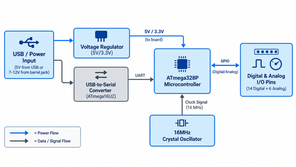
Internally, the Arduino Uno’s pins connect through four main functional blocks:
- Power regulation block converts USB (5V) or barrel jack input (7–12V) into stable 5V and 3.3V for the board and connected components.
- ATmega328P microcontroller the central chip that reads digital/analog input, runs the uploaded code, and controls output pins.
- USB-to-serial converter allows the board to communicate with a computer for programming and serial monitor data.
- Crystal oscillator (16MHz) provides the timing clock the microcontroller uses to execute instructions.
Understanding this block diagram helps explain why certain pins behave the way they do for example, why pins 0 and 1 conflict with USB uploads (they share the same serial line as the USB-to-serial converter).
Digital pins vs analog pins: what’s the difference?
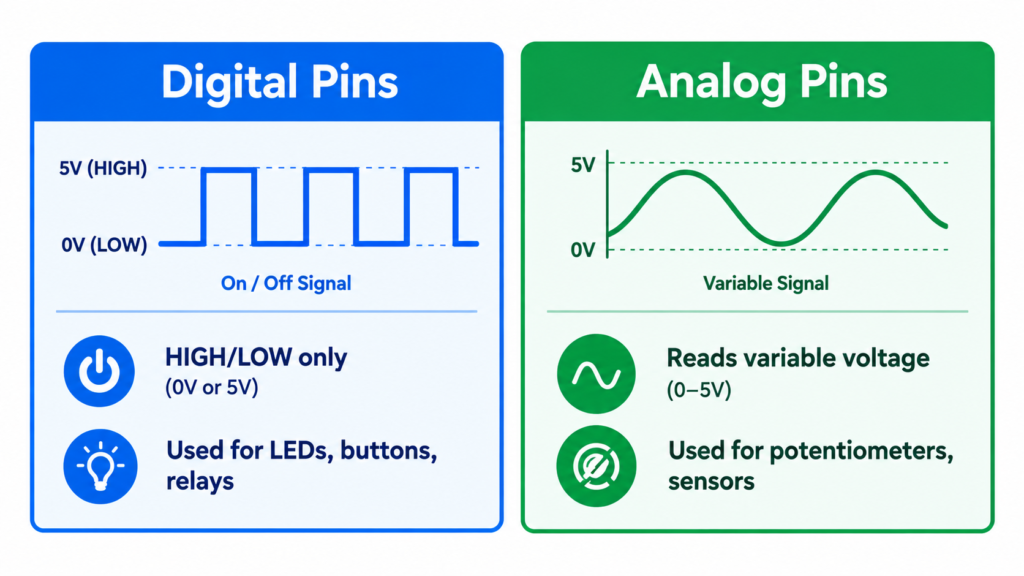
- Digital pins (0–13) read or write only two states: HIGH (5V) or LOW (0V). Used for buttons, LEDs, relays, and digital sensors.
- Analog pins (A0–A5) read a range of voltage values (0–5V, mapped internally to 0–1023) using a 10-bit ADC (Analog-to-Digital Converter). Used for sensors like potentiometers, LDRs, and temperature sensors that output a variable voltage.
- PWM pins (marked with ~) are digital pins that simulate analog output by rapidly switching HIGH/LOW, useful for dimming LEDs or controlling motor speed.
Power pin ratings (important for safe wiring)
| Pin | Voltage | Max current |
|---|---|---|
| 5V | 5V regulated | ~500mA (shared across board) |
| 3.3V | 3.3V regulated | ~50mA |
| VIN | 7–12V (recommended) | Depends on external supply |
| Any digital/analog pin | 5V logic | 20mA recommended, 40mA absolute max |
Exceeding these limits especially drawing too much current directly from an I/O pin (e.g., powering a motor directly instead of through a driver) is one of the most common ways beginners damage their Arduino Uno.
Common pinout mistakes to avoid
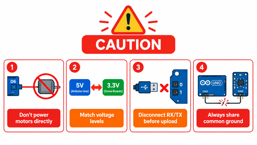
- Using pins 0 and 1 while uploading code disconnect anything wired to RX/TX before uploading a sketch, or uploads will fail.
- Powering motors/relays directly from I/O pins always use a transistor, relay module, or motor driver (like L298N) instead.
- Mixing up 5V and 3.3V some sensors (like certain WiFi/Bluetooth modules) require 3.3V logic and can be damaged by 5V.
- Forgetting analog pins can be digital too A0–A5 can be used as digital pins 14–19 in code when you run out of digital pins.
- Not sharing a common ground when using external power for motors/modules, the external GND must connect to the Arduino’s GND.
Frequently asked questions
How many pins does Arduino Uno have?
Arduino Uno has 20 usable I/O pins: 14 digital pins (0–13) and 6 analog pins (A0–A5), plus additional power and communication pins (5V, 3.3V, GND, VIN, AREF).
Which Arduino Uno pins support PWM?
Pins 3, 5, 6, 9, 10, and 11 support PWM (Pulse Width Modulation) output, marked with a tilde (~) symbol on the board silkscreen.
Can analog pins be used as digital pins on Arduino Uno?
Yes. A0–A5 can be used as digital pins 14–19 in code, giving extra digital I/O when needed.
What is the maximum current an Arduino Uno pin can supply?
Each I/O pin can safely supply up to 20mA continuously, with an absolute maximum of 40mA. The total current across all pins should not exceed 200mA.
What is pin 13 used for on Arduino Uno?
Pin 13 is connected to the onboard LED (marked “L”) in addition to its normal digital I/O function, making it commonly used for blink tests and status indicators.