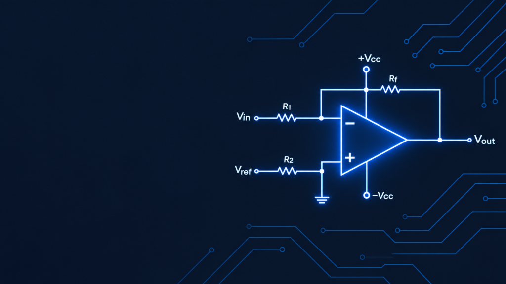
An operational amplifier (op-amp) is a high-gain, direct-coupled voltage amplifier with two inputs (inverting and non-inverting) and one output. It normally works with negative feedback, which sets its gain and behaviour. Op-amps are the basic building blocks of analog electronics. By changing the feedback components you can make one act as an amplifier, adder, integrator, comparator, filter or oscillator.
Key takeaways
- An op-amp has 2 inputs, 1 output and 2 supply pins.
- Ideal op-amp: infinite gain, infinite input resistance, zero output resistance, infinite bandwidth.
- Practical op-amp (IC 741): open-loop gain about 2×10⁵, input resistance about 2 MΩ, output resistance about 75 Ω.
- Negative feedback makes real op-amps behave close to ideal.
What is the block diagram of an op-amp?
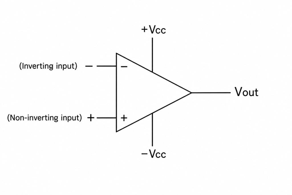
An IC op-amp has four stages connected in series:
| Stage | Circuit | Function |
|---|---|---|
| 1. Input stage | Differential amplifier | Gives high input impedance, high CMRR and most of the voltage gain; rejects noise common to both inputs |
| 2. Intermediate stage | Cascaded gain stage(s) | Adds more voltage gain; direct-coupled, so it also amplifies DC |
| 3. Level shifter | Emitter follower / current source | Shifts the DC level so the output is 0 V when both inputs are 0 V |
| 4. Output stage | Push-pull (class AB) amplifier | Gives low output impedance, high current capability and a large output swing |
Text description of the diagram: the input signal enters the differential amplifier, passes through the gain stage and level shifter, and leaves through the push-pull output stage.
What is the symbol of an op-amp?
The op-amp is drawn as a triangle pointing right.
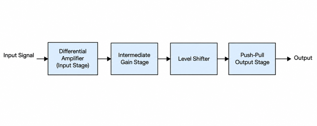
- Inverting input (−): the output is amplified and shifted by 180°.
- Non-inverting input (+): the output is amplified and in phase.
- Output (Vout): single-ended output on the right.
- +Vcc and −Vcc: positive and negative supply pins, often left out of simplified drawings.
Output voltage: Vout = A₀ (V₊ − V₋), where A₀ is the open-loop gain.
The + and − signs only mark phase behaviour. They do not mean the input voltage must be positive or negative.
What is the pin diagram of the IC 741?
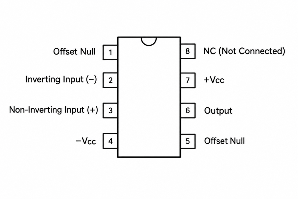
The IC 741 is an 8-pin op-amp, the most common one in college labs.
| Pin | Function |
|---|---|
| 1, 5 | Offset null |
| 2 | Inverting input (−) |
| 3 | Non-inverting input (+) |
| 4 | −Vcc (negative supply) |
| 6 | Output |
| 7 | +Vcc (positive supply) |
| 8 | Not connected |
What is the polarity convention of an op-amp?
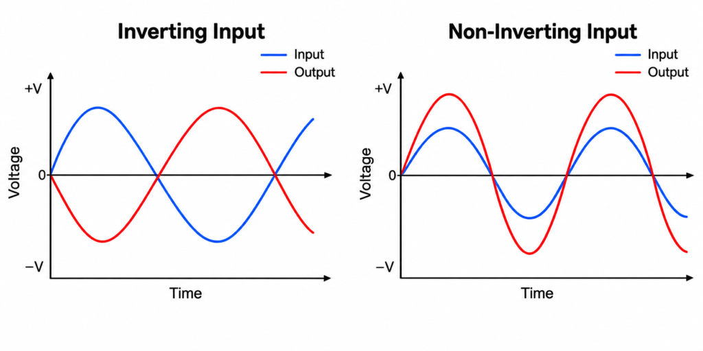
A signal at the inverting terminal comes out amplified and 180° out of phase. A signal at the non-inverting terminal comes out amplified and in phase. All voltages are measured with respect to a common ground reference.
What are the characteristics of an ideal op-amp?
An ideal op-amp is a theoretical model used to simplify circuit analysis:
- Open-loop voltage gain (A₀) = ∞
- Input resistance (Rᵢ) = ∞, so it draws no current from the source
- Output resistance (R₀) = 0, so the output does not drop under load
- Bandwidth = ∞, so all frequencies are amplified equally
- CMRR = ∞, so common-mode noise is completely rejected
- Slew rate = ∞, so the output follows the input instantly
- Output = 0 V when both inputs are equal (zero offset)
- No drift with temperature
What are the characteristics of a practical op-amp?
A real op-amp has finite limits. Values below are typical for the IC 741. Check the datasheet for your exact IC.
| Parameter | Ideal | Practical (741 typical) |
|---|---|---|
| Open-loop gain | ∞ | about 200,000 (2×10⁵) |
| Input resistance | ∞ | about 2 MΩ |
| Output resistance | 0 | about 75 Ω |
| Bandwidth (unity gain) | ∞ | about 1 MHz |
| CMRR | ∞ | about 90 dB |
| Slew rate | ∞ | about 0.5 V/µs |
| Output with zero input | 0 V | small offset voltage |
| Temperature drift | 0 | small drift present |
How does negative feedback improve an op-amp?
Open-loop gain is huge but unstable, so real circuits feed part of the output back to the inverting input. This gives stable, predictable gain, higher input resistance, lower output resistance and wider bandwidth. It also produces a virtual short: the two inputs sit at nearly the same voltage, so with the non-inverting input grounded, the inverting input acts as a virtual ground.
Gain formulas
- Inverting amplifier: Gain = −Rf / R1
- Non-inverting amplifier: Gain = 1 + Rf / R1
Example: Rf = 10 kΩ, R1 = 1 kΩ, input = 0.5 V (inverting). Gain = −10, so Vout = −5 V.
What are the applications of an op-amp?
- Linear: inverting and non-inverting amplifiers, voltage follower, summing amplifier, integrator, differentiator, instrumentation amplifier, active filters, voltage-to-current and current-to-voltage converters
- Non-linear: comparators, Schmitt trigger, logarithmic and anti-logarithmic amplifiers, analog multipliers, sample-and-hold circuits, square and triangular wave generators
Common ICs: 741, LM358, LM324, TL072, NE5532.
Frequently asked questions
What is the full form of op-amp?
Operational amplifier.
Why is it called an operational amplifier?
It was first used in analog computers to perform mathematical operations such as addition, subtraction, integration and differentiation.
What is the ideal value of input resistance and output resistance?
Input resistance is infinite and output resistance is zero.
What is CMRR in an op-amp?
The Common-Mode Rejection Ratio measures how well the op-amp rejects signals common to both inputs. Higher is better.
What is slew rate?
The maximum rate of change of the output voltage, in V/µs. It limits how fast the output can follow a changing input.
What is a virtual ground?
With negative feedback and the non-inverting input grounded, the inverting input sits at almost 0 V without being physically connected to ground.