A servo motor is controlled with Arduino using the built-in Servo library, which sends a PWM signal to rotate the motor to a specific angle (0°–180°) using a single signal wire, while a temperature sensor like the LM35 or DHT11 is read using an analog or digital pin to report temperature in real time on the Serial Monitor or an LCD. Both are among the most common first “sensor + actuator” projects for students because they use only three to four wires, require no external library beyond what Arduino IDE includes or offers through the Library Manager, and directly demonstrate the read-input/control-output logic that underlies most embedded systems coursework.
Key takeaways
- A standard hobby servo motor rotates between 0° and 180°, controlled by a PWM signal on one wire.
- Servos need a separate 5V power source for anything beyond a single small servo powering multiple servos directly from the Arduino’s 5V pin can cause voltage drops and erratic behavior.
- LM35 is an analog temperature sensor (reads a voltage that scales linearly with °C); DHT11 is a digital sensor (reads temperature and humidity together via a single data pin).
- Both projects use different Arduino pin types: servo uses a PWM digital pin, LM35 uses an analog pin, DHT11 uses any digital pin (via library).
Project 1: Controlling a servo motor with Arduino
Components needed
| Component | Quantity | Notes |
|---|---|---|
| Arduino Uno (or Nano) | 1 | Any PWM-capable digital pin works |
| SG90 (or similar) micro servo | 1 | Standard 3-wire hobby servo |
| Jumper wires | 3 | Signal, power, ground |
| External 5V power (for multiple servos) | Optional | Not needed for a single small SG90 servo |
Wiring diagram
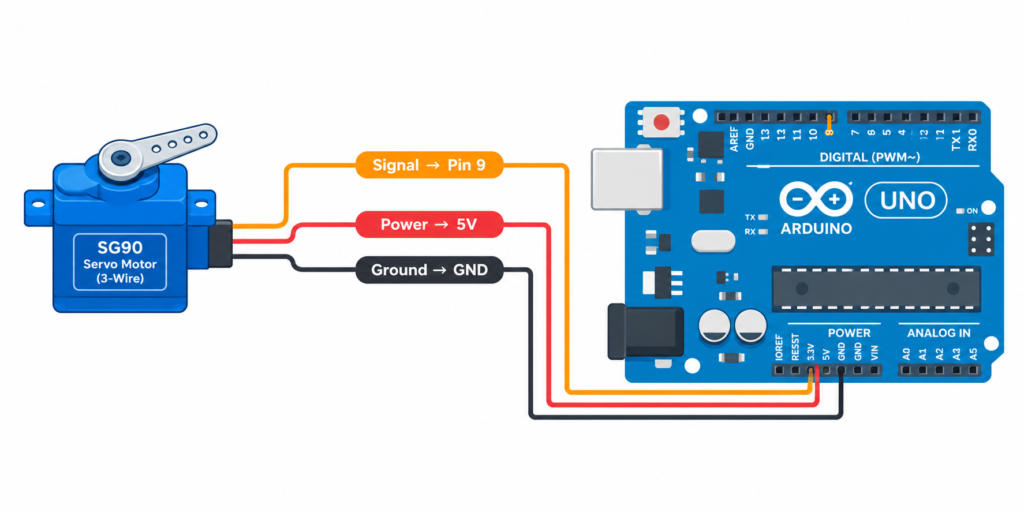
| Servo Wire | Color (typical) | Connects to |
|---|---|---|
| Signal | Orange/Yellow | Arduino digital PWM pin (e.g., pin 9) |
| Power (+) | Red | Arduino 5V |
| Ground (−) | Brown/Black | Arduino GND |
Arduino code: sweep servo 0°–180°
cpp
#include <Servo.h>

Servo myServo;

void setup() {
  myServo.attach(9); // Signal wire connected to pin 9
}

void loop() {
  for (int angle = 0; angle <= 180; angle++) {
    myServo.write(angle);
    delay(15);
  }
  for (int angle = 180; angle >= 0; angle--) {
    myServo.write(angle);
    delay(15);
  }
}
What each key function does:
myServo.attach(9)tells the library which pin sends the PWM control signal.myServo.write(angle)rotates the servo shaft to the specified angle (0–180°).- The two
forloops sweep the servo smoothly from 0° to 180° and back, with a 15ms delay between each degree of movement.
Common servo problems and fixes
Problem: Servo jitters or moves erratically
Fix: This is almost always a power issue the Arduino’s 5V pin cannot supply enough current for the servo’s movement spikes. Use a separate 5V power supply for the servo, with a shared ground between it and the Arduino.
Problem: Servo doesn’t reach full 0°–180° range
Fix: Some servos have a narrower usable range; use myServo.writeMicroseconds() instead of write() for finer control, adjusting the pulse width (typically 500–2500 microseconds) to match your specific servo’s range.
Project 2: Reading temperature with Arduino
Components needed
| Component | Quantity | Notes |
|---|---|---|
| Arduino Uno (or Nano) | 1 | Any analog pin (LM35) or digital pin (DHT11) works |
| LM35 temperature sensor OR DHT11 sensor | 1 | LM35 = analog, simpler; DHT11 = digital, adds humidity |
| 10kΩ resistor | 1 (DHT11 only) | Pull-up resistor for DHT11 data line |
| Jumper wires | 3 | Power, ground, signal |
Wiring diagram (LM35 analog method)
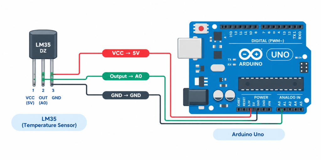
| LM35 Pin | Connects to |
|---|---|
| VCC | Arduino 5V |
| GND | Arduino GND |
| Output (Vout) | Arduino analog pin A0 |
Arduino code: LM35 temperature reading
cpp
const int sensorPin = A0;

void setup() {
  Serial.begin(9600);
}

void loop() {
  int rawValue = analogRead(sensorPin);
  float voltage = rawValue * (5.0 / 1023.0);
  float temperatureC = voltage * 100; // LM35: 10mV per °C

  Serial.print("Temperature: ");
  Serial.print(temperatureC);
  Serial.println(" °C");

  delay(1000);
}
What each key line does:
analogRead(sensorPin)reads the raw analog value (0–1023) representing 0–5V.voltage = rawValue * (5.0 / 1023.0)converts the raw value into an actual voltage.temperatureC = voltage * 100converts voltage to °C, since the LM35 outputs exactly 10mV per degree Celsius.
Wiring diagram (DHT11 digital method)
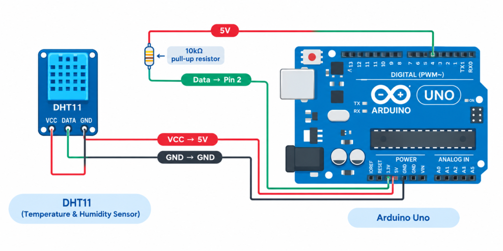
| DHT11 Pin | Connects to |
|---|---|
| VCC | Arduino 5V |
| GND | Arduino GND |
| Data | Arduino digital pin 2 (with 10kΩ pull-up resistor to 5V) |
Arduino code: DHT11 temperature + humidity reading
cpp
#include <DHT.h>

#define DHTPIN 2
#define DHTTYPE DHT11

DHT dht(DHTPIN, DHTTYPE);

void setup() {
  Serial.begin(9600);
  dht.begin();
}

void loop() {
  float temperature = dht.readTemperature();
  float humidity = dht.readHumidity();

  if (isnan(temperature) || isnan(humidity)) {
    Serial.println("Failed to read from DHT sensor!");
    return;
  }

  Serial.print("Temperature: ");
  Serial.print(temperature);
  Serial.print(" °C  Humidity: ");
  Serial.print(humidity);
  Serial.println(" %");

  delay(2000);
}
Note: the DHT.h library must be installed first via Tools → Manage Libraries → search “DHT sensor library” by Adafruit.
LM35 vs DHT11: which should you use?
| Feature | LM35 | DHT11 |
|---|---|---|
| Reads | Temperature only | Temperature + humidity |
| Signal type | Analog | Digital (single-wire protocol) |
| Accuracy | ±0.5°C, more precise | ±2°C, less precise |
| Reading speed | Instant | ~1 reading per second (slower) |
| Extra library needed | No | Yes (DHT library) |
| Best for | Precise, temperature-only projects | Weather stations, humidity-dependent projects |
Combining both projects: a servo-controlled fan/vent concept
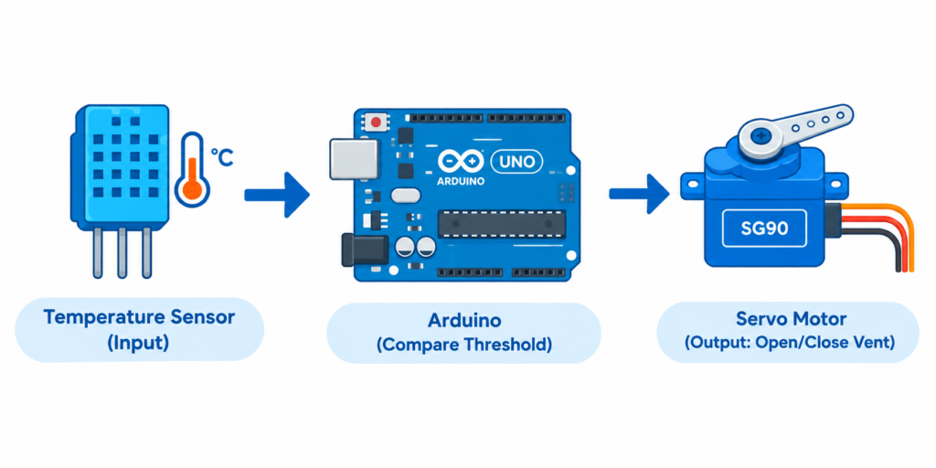
A common next-step student project combines these two: read temperature with an LM35 or DHT11, then use the reading to control a servo (e.g., opening a vent flap when temperature crosses a threshold):
cpp
#include <Servo.h>

Servo myServo;
const int sensorPin = A0;

void setup() {
  myServo.attach(9);
  Serial.begin(9600);
}

void loop() {
  int rawValue = analogRead(sensorPin);
  float temperatureC = (rawValue * (5.0 / 1023.0)) * 100;

  if (temperatureC > 30.0) {
    myServo.write(90); // Open vent
  } else {
    myServo.write(0);  // Close vent
  }

  Serial.println(temperatureC);
  delay(1000);
}
This pattern read sensor, compare threshold, drive actuator is the basis for most automation and IoT lab projects.
Frequently asked questions
Why does my servo motor jitter when connected to Arduino?
This is usually caused by insufficient power from the Arduino’s 5V pin. Use a separate 5V power supply for the servo with a shared ground connection to the Arduino.
What is the difference between LM35 and DHT11 sensors?
LM35 is an analog sensor that reads only temperature with higher precision (±0.5°C), while DHT11 is a digital sensor that reads both temperature and humidity with lower precision (±2°C).
How do I control a servo motor’s angle with Arduino?
Use the built-in Servo library: call myServo.attach(pin) in setup, then myServo.write(angle) anywhere in your code to rotate the servo to a specific angle between 0 and 180 degrees.
Can I power multiple servos from the Arduino board itself?
Not reliably. A single small servo (like an SG90) usually works from the Arduino’s 5V pin, but multiple servos or larger servos require a separate external 5V power supply to avoid voltage drops and erratic movement.
Why is my DHT11 sensor returning “nan” or failed readings?
Check that the pull-up resistor (10kΩ) is correctly wired between the data pin and 5V, confirm the correct pin number is set in code, and allow at least 1–2 seconds between readings, since DHT11 cannot be polled faster than roughly once per second.