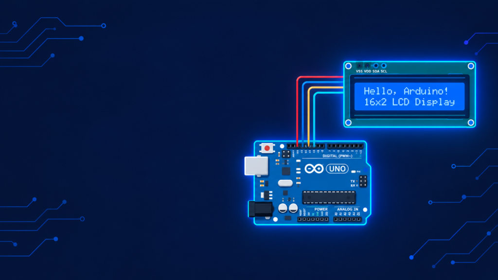
A 16×2 LCD display is interfaced with Arduino by connecting its data pins (D4–D7), control pins (RS, Enable), power pins (VCC, GND), and a contrast-adjustment potentiometer (V0) to the Arduino board, then using the built-in LiquidCrystal library to send text to the screen with just a few lines of code. This is one of the most common student electronics projects because it teaches parallel data communication, library usage, and character-based display logic using inexpensive, widely available hardware (a 16×2 LCD costs roughly $2–4 / NPR 250–400).
Key takeaways
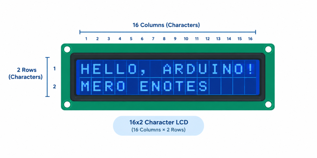
- A 16×2 LCD has 16 columns and 2 rows, displaying up to 32 characters at once.
- Most 16×2 LCDs use the HD44780 driver chip, which the Arduino’s built-in
LiquidCrystallibrary is designed to control directly. - Wiring uses 4-bit mode (4 data pins) in most tutorials to save Arduino pins, instead of 8-bit mode (8 data pins).
- A potentiometer is required to control screen contrast without it, the display often appears blank even when working correctly.
- An I2C adapter module can reduce the wiring from ~12 pins down to just 2 (SDA, SCL) for larger projects needing extra pins.
Components needed
| Component | Quantity | Notes |
|---|---|---|
| Arduino Uno (or Nano) | 1 | Any ATmega328P-based board works |
| 16×2 LCD display (HD44780-based) | 1 | Blue or green backlight, both work identically |
| 10kΩ potentiometer | 1 | For contrast adjustment |
| Breadboard | 1 | For prototyping connections |
| Jumper wires | ~12 | Male-to-male |
| 220Ω resistor (optional) | 1 | For backlight current limiting (some LCDs include this already) |
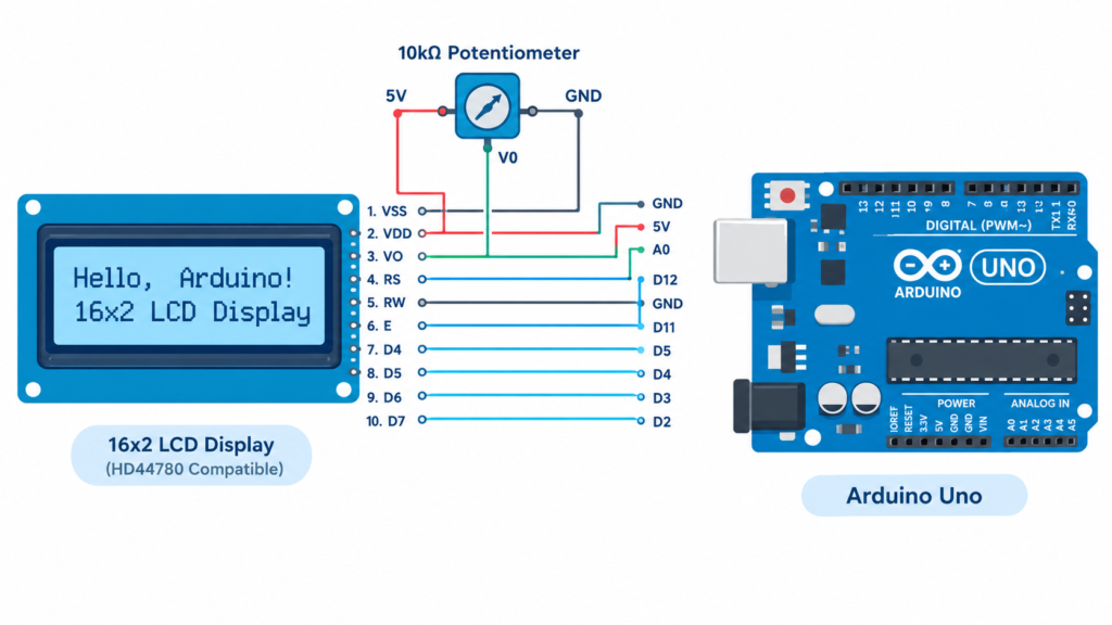
Wiring diagram: 16×2 LCD to Arduino (4-bit mode)
| LCD Pin | Function | Connects to |
|---|---|---|
| VSS | Ground | Arduino GND |
| VDD | Power (+5V) | Arduino 5V |
| V0 | Contrast control | Potentiometer wiper |
| RS | Register Select | Arduino digital pin 12 |
| RW | Read/Write | Arduino GND (tied LOW write mode only) |
| E | Enable | Arduino digital pin 11 |
| D4 | Data bit 4 | Arduino digital pin 5 |
| D5 | Data bit 5 | Arduino digital pin 4 |
| D6 | Data bit 6 | Arduino digital pin 3 |
| D7 | Data bit 7 | Arduino digital pin 2 |
| A (Anode) | Backlight + | Arduino 5V (through 220Ω resistor if not built-in) |
| K (Cathode) | Backlight − | Arduino GND |
The potentiometer’s two outer legs connect to 5V and GND, with the middle leg (wiper) going to the LCD’s V0 pin this is what lets you physically turn the knob to adjust screen contrast.
Arduino code: displaying text on the LCD
cpp
#include <LiquidCrystal.h>

// Initialize the library with the interface pins used above
LiquidCrystal lcd(12, 11, 5, 4, 3, 2);

void setup() {
  lcd.begin(16, 2);           // Set up the LCD's number of columns and rows
  lcd.print("Hello, Arduino!"); // Print a message to the first row
}

void loop() {
  lcd.setCursor(0, 1);         // Move cursor to column 0, row 1 (second row)
  lcd.print("Mero eNotes");    // Print a message to the second row
}
What each key function does:
LiquidCrystal lcd(12, 11, 5, 4, 3, 2)tells the library which Arduino pins connect to RS, Enable, D4, D5, D6, D7 (in that order).lcd.begin(16, 2)configures the display size (16 columns, 2 rows). Must match your actual LCD size.lcd.print()writes text starting at the current cursor position.lcd.setCursor(column, row)moves the cursor before writing, since rows/columns are zero-indexed (row 0 = top, row 1 = bottom).
Using an I2C module to simplify wiring
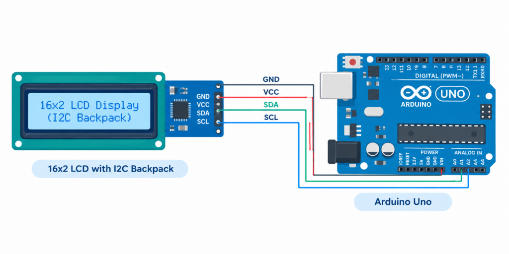
For projects where Arduino pins are limited (e.g., combining an LCD with several sensors), an I2C backpack module (a small add-on board soldered onto the back of the LCD) reduces the wiring to just 4 pins:
| I2C Module Pin | Connects to |
|---|---|
| GND | Arduino GND |
| VCC | Arduino 5V |
| SDA | Arduino A4 (Uno/Nano) |
| SCL | Arduino A5 (Uno/Nano) |
cpp
#include <Wire.h>
#include <LiquidCrystal_I2C.h>

LiquidCrystal_I2C lcd(0x27, 16, 2); // I2C address may be 0x27 or 0x3F

void setup() {
  lcd.init();
  lcd.backlight();
  lcd.print("Hello, Arduino!");
}

void loop() {
}
Note: the I2C address (0x27 or 0x3F are most common) varies by module manufacturer if the screen doesn’t respond, run an I2C scanner sketch (widely available online) to detect the correct address.
Common LCD problems and fixes
Problem: Screen backlight is on, but no text appears
Fix: Adjust the contrast potentiometer this is the single most common cause of a “blank” LCD that is otherwise wired correctly.
Problem: Garbled or random characters on screen
Fix: Double-check the RS, Enable, and data pin wiring matches exactly what’s declared in LiquidCrystal lcd(...) in your code a single swapped pin causes garbled output.
Problem: I2C LCD shows nothing and Serial Monitor shows no I2C device found
Fix: Confirm SDA/SCL wiring (A4/A5 on Uno/Nano) and try both common I2C addresses (0x27 and 0x3F) since manufacturers vary.
Problem: Text appears but backlight doesn’t turn on
Fix: Check the backlight anode/cathode wiring and confirm the current-limiting resistor (if separate) isn’t wired backward or open.
Project ideas using an LCD with Arduino
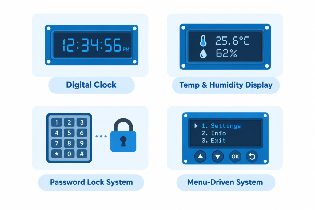
- Digital clock: combine with an RTC (real-time clock) module to display live time/date
- Temperature and humidity display: pair with a DHT11/DHT22 sensor for a live weather readout
- Password/keypad lock system: combine with a 4×4 keypad for a simple access-control lab project
- Menu-driven system: use buttons to scroll through options displayed on the LCD, useful for BCA/BE lab final projects demonstrating state-machine logic
Frequently asked questions
What driver chip do most 16×2 LCDs use?
Most 16×2 character LCDs use the HD44780 driver chip (or a compatible clone), which is what Arduino’s built-in LiquidCrystal library is designed to communicate with.
Why is my LCD screen blank even though it’s wired correctly?
The most common cause is incorrect contrast adjustment turn the connected potentiometer while the Arduino is powered to bring the text into view.
Can I use an LCD with fewer Arduino pins?
Yes. An I2C backpack module reduces wiring from about 12 pins down to just 4 (GND, VCC, SDA, SCL), using the LiquidCrystal_I2C library instead of the standard LiquidCrystal library.
What is the difference between 4-bit and 8-bit LCD mode?
4-bit mode uses only 4 data pins (D4–D7) and sends each byte of data in two steps, while 8-bit mode uses all 8 data pins (D0–D7) and sends data in one step; 4-bit mode is used in almost all Arduino tutorials to save pins, with only a small speed trade-off.
How do I find the correct I2C address for my LCD module?
Run a free I2C scanner sketch (widely available in Arduino example libraries and tutorials), which checks common addresses on the I2C bus and prints the detected address to the Serial Monitor.